Okay - Here is another metalworking project I did at Xerocraft. This one was done on the milling machine.
One of the tools that we were missing for the metal lathe was a boring tool that could be used to make precision holes, tapered holes, or holes that are larger than available drills. Tool holders that fit the KDK quick change tool post on our lathe are hard to find and pretty expensive, so I decided I would make my own.
Rather than go all out and create a holder that fits the dovetail on the tool post, I decided to go the easy route and create a holder that would fit into the 1/2" slot on one of the KDK tool holders and hold a 1/2" round boring bar.
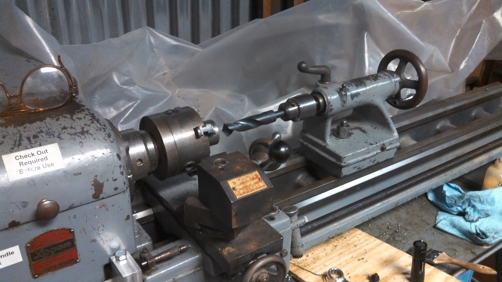
The design is very simple. Its a block of aluminium (because that is what I had on hand, and its easy to work with). One side is drilled through with a 1/2" hole, and the other is milled to a 1/2" width to fit in the slot of the tool holder. The part that fits into the toolholder is slit to allow the setscrews that hold it in the toolholder to compress the hole in order to hold the boring bar. The photo above shows the boring tool as it is mounted for use. The shiny part is what I built.
I started by cutting a chunk of 6061 aluminium to the approximate size, then squaring it in the mill. Next I marked and drilled the hole for the boring tool, first with a center drill, then a small bit to establish a guide hole, and finally the 1/2" drill to fit the boring bar. I did not ream the hole to size because the precision is not needed for this purpose.
Next I mounted the block directly to the mill table using a 1-2-3 block and some strap/step clamps. I aligned the block to the axis of the mill with a dial indicator, then cut the steps for the part that mounts into the holder. I used successive passes to get to the desired depth. If I were to do it again, I would likely side mill at approximately the same depth to use more of the milling cutter.
I flipped the piece and aligned and cut the other side in the same way.
The final step was to mount a slitting saw with the same clamping setup, and cut a slit on the center line of the 1/2" width slot to the boring bar hole to provide a method for holding the boring bar.
When completed, the boring bar would slide into the hole at the appropriate depth and the 1/2" part would fit into the slot of the tool holder and get clamped into place. This holds both the block in place, and by compressing the slit in the center, holds the boring bar in place.
The photo below shows an example of the boring bar holder mounted to bore a hole on the lathe.
Tuesday, November 6, 2012
Sunday, November 4, 2012
Metalworking: Slitting Saw Arbor
Okay, so this is not an electronics project, but it is my blog, and lately I've been spending my hobby time doing metalworking projects at Xerocraft, Tucson's local Hackerspace.
We have a old Logan Lathe and a generic chinese Mill Drill that I've been using primarily to make tooling for the lathe and mill.
Its been a lot of fun reviving the love of machining that I learned from my middle school (called Jr High back then) metal shop class.
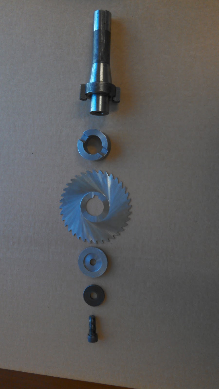
This project was to build a bushings that allow our R8 shell mill holder to be used for 1" arbor hole slitting saws (like the one on the picture above), or other side milling cutters.
There were two parts needed to use the arbor for slitting saws. Both started as a 1-5/8" diameter 1117 free machining steel rod.
The main bushing started as a solid piece of steel. I mounted it in the three jaw chuck on the lathe and faced both sides square and flat.
Next I center drilled it and drilled progressively large holes through the center in 1/8 increments starting with 1/4" and ending with this 7/8" reduced shank (aka Silver and Deming) bit.
Next I set up a boring tool in the boring bar toolholder I made on the mill, and bored the remaining 1/8" to get the hole to fit the tool with a very close fit. I did this by first boring to .995", then test-fit and bored a few mils more until I got the desired fit.
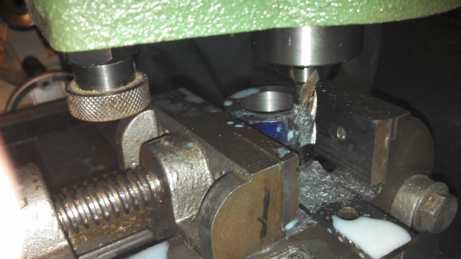
The next step was to coat it with blue dye and mark it for milling. I carefully mounted it in the vice properly aligned so I could mill it directly down the center line for the alignment slots that keep it from turning on the arbor under the milling forces. This required some careful setup, but was a it easy milling operation. I actually broke a endmill while milling this. The slotting operation in steel makes for a much heavier chipload that could not effectively clear out of slot. If you look closely at the picture above, you can see the very fine chips caused by the cutter cutting its own chips over and over instead of clearing them out of the slot.
I cut the slot a bit too deep and used the lathe to adjust the depth of the slot by facing off the excess material. Next I turned it around and faced the other size to get the length exactly right. That finished the first piece.
The second piece was done entirely on the lathe. First I mounted a small piece of the same 1-5/8" rod in the three jaw chuck and faced one side flat and square. I drilled a clearance hole for a 3/8" drill. Again with the same facing tool, I faced out a notch so the part fit perfectly into the top of the bushing.
Next I flipped the piece around and used a different tool to face out an indentation starting at the center hole to fit perfectly over the top of the arbor.
The two pieces fit together in two different ways depending on the width of the slitting or slotting saw used. If a thin slitting saw such as the one in the picture below is used, the concave side is used so the saw is held tightly on the arbor. If a thicker saw is used, the convex side is used to give support of the top on the bottom from the arbor, and on top from the machined piece.
The whole part goes together as shown below.
Subscribe to:
Posts (Atom)


